|
|
Post by Lee Martin on Feb 7, 2014 14:06:35 GMT -5
Calculating Action Rigidity _____________________________________ When a rifle fires, the action is stressed by lateral and axial components. These forces transverse the lugs, bolt body, the receiver, and of course the barrel. They’re micro in nature but do cause stretching and bending of the steel. By countering those stresses we lower deflection and harmonic inconsistencies. Better accuracy should follow. The barrel is equally, if not more important in minimizing these nodes. Length, tenon size, thread specs, and diameter all combine to damper vibration. Rifles and precision shooting naturally leads to talk of rigidity. Early benchresters knew short and stout resisted on-axis force better than long and thin. Physics also taught us about fixed beams and pre-loading the free end. It’s a decent representation of a barreled action but works on length and diameter alone. It doesn’t account for other inherent properties such as port size and lug passages. This made analyzing stiffness subjective at best. Then math came to the rescue. A receiver’s rigidness is measured at the middle of the loading port. Tests from the 50’s and 60’s picked that area because it’s the weakest segment. This was further standardized by Stuart Otteson. Apart from the lug passages, our action lacks raceways. Just think of it as a tube with a hole milled in one wall. The simplified geometry makes inertia much easier to figure (inertia quantifies metal’s ability to resist changes to its physical state). So the cross-section is approximated by a circular ring of known radii minus the loading slot: Area = pi(R1^2 – R2^2) Martin action: OD1 = 1.450”, R1 = 0.7250” OD2 = 0.875”, R2 = 0.4375” Ring area = 1.0501 square inches 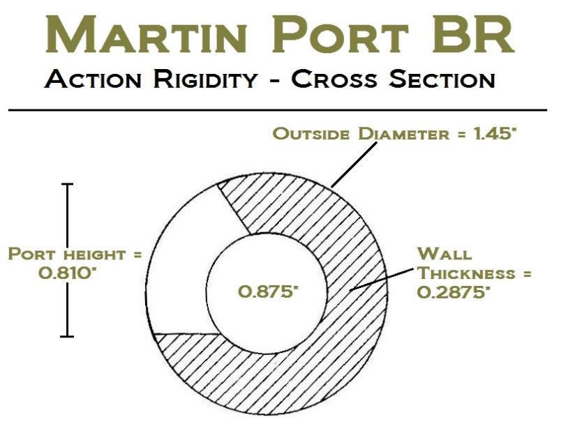 The port’s cross-sectional area (A) is found using an arc cosine function. A = 0.2352. Total cross-sectional area at the mid-point then becomes: 1.0501 – 0.2352 = 0.8149 square inches Inertia defined: I = pi/64[(OD1^4 – OD2^4)] = 3.1416/64[(1.450^4 – 0.875^4)] = 0.1882 Steel’s density equals 0.28 lb/square inch so we can calculate unit weight as well: Unit Weight = pi/4[(OD1^2 – OD2^2)] x Density = (3.1416/4) x (1.45^2 – 0.875^2) x (0.28) = 0.293 lbs/in We also need 4140’s elastic modulus, or its tendency to be deformed by force. Multiple inertia (I) by the modulus of elasticity (E) and we have rigidity (E for steel = 30 x 10^6) Rigidity = I x E = (0.1882) x (30 x 10^6) = 5.67 x 10^6 in2-lb But 5.7 x 10^6 in2-lb is meaningless until you compare it to known entities. This shows the degree of stiffness achieved over factory designs. 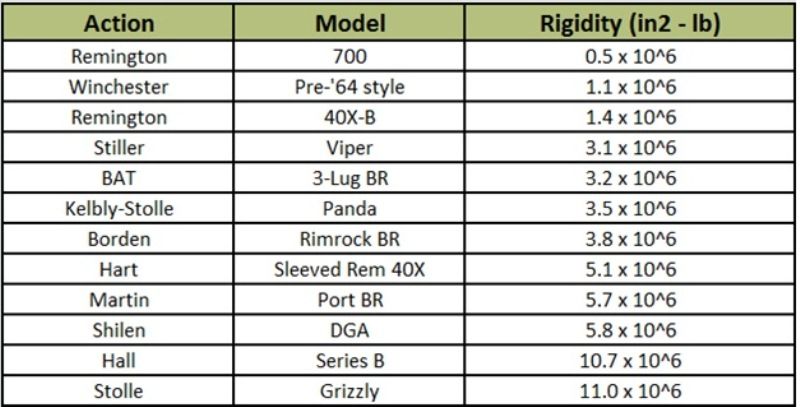 Our receiver stacks-up well with other BR models and I attribute it to the Hall pattern. Consider the Stiller Viper at 8.5” in length and ~ 1.40” in diameter. Our Martin BR is just under 9.0” with an O.D. of 1.45”. Despite the dimensional similarities ours is nearly twice as rigid. Benchrest is full of topics you can over-think. I don’t believe action rigidity is one of them however. It’s an integral part of precision shooting. If it weren’t there would be no rail-gun class. When I get into barrel harmonics I’ll draw upon some of above equations. Keep these ideas as a placeholder for now. -Lee www.singleactions.com"Building carpal tunnel one round at a time" |
|
|
|
Post by Lee Martin on Feb 20, 2014 15:36:21 GMT -5
Step 27 – The Firing Pin _______________________________________ Any challenging gun project presents an obstacle or two. This action is no different. After the bolt was bored end-to-end we machined the firing pin from pre-hardened drill rod. The tip was set to 0.071” for the 0.073” opening. Upon installation a slight amount of rub was revealed at 9:00; slight as in less than a half-thousandth. In all likelihood the tiny drill bit walked out. That may pass on a hunting rifle but for precision shooting it’s a deal breaker. The workaround involved bushing the hole, something that was a blessing in disguise. The bushing was lathed 0.20” o.d. and center drilled to 0.070”. A boring bar recessed the face and we went small at 0.199”. Press fitting the collar with a Loctite seal gave very positive seating. The bushing offers two advantages: 1) I wanted to run a smaller tip, viz. 0.065” – 0.068”. Dad makes his over 0.070” so this mishap allowed me to convince him less is more (when I get into primers you’ll see why I lobbied for under 70 thou) 2) The bushing can be tapped out with a punch (the rear edge is exposed from the back bolt passage). Not that I’ll need to, but now I can experiment with different pin diameters. Our starting point is quarter inch drill rod: 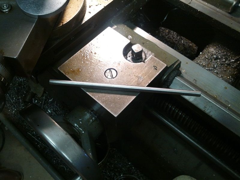 Machining the pin assembly: 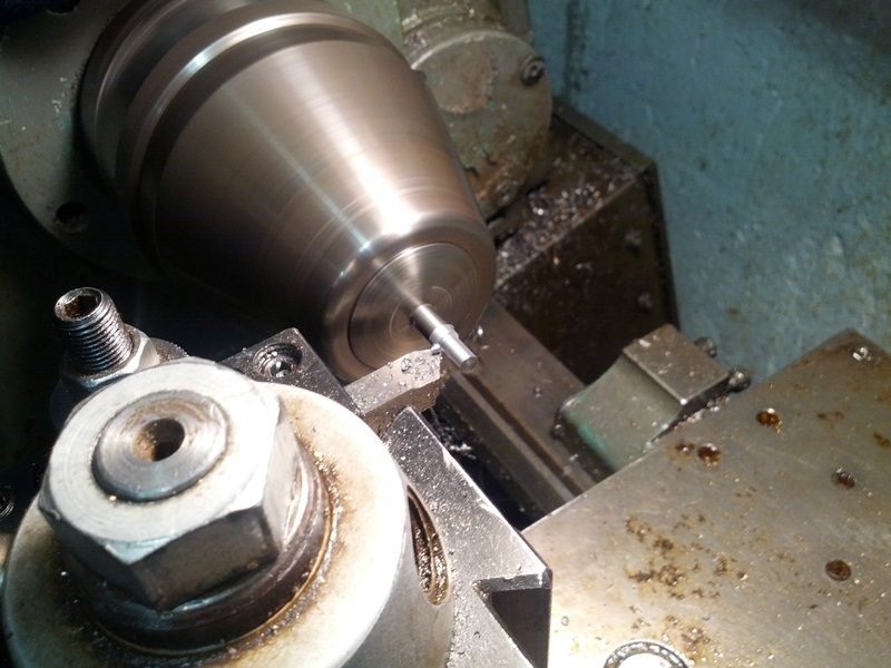 The tip is 0.068” x 0.400” long. With a 0.070” bushing, the 0.002” total clearance, or 0.001” per side, is retained: 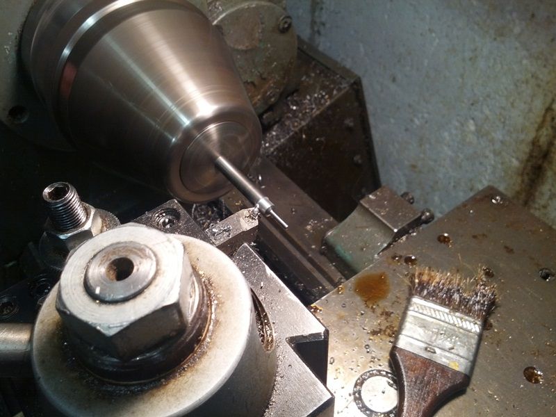 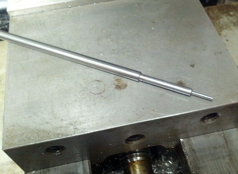 The next step is 0.180” x 1.50” and we threaded the last 0.40” for an adjustable sleeve: 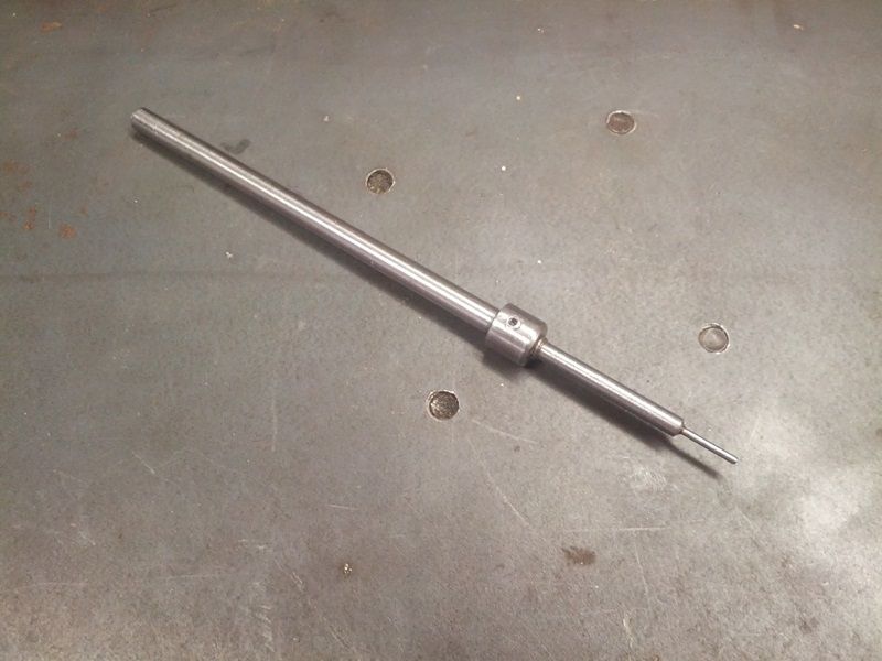 The collar is something my dad designed when he built our first BR action in 1987. I can’t say he’s the only one to do this, but I’ve never seen another like it. The slick thing is the insert acts as a travel stop. The bushing threads onto the rod and is further locked with a screw. By moving it in or out, firing pin protrusion can be altered. Ours is set for 0.055”. -Lee www.singleactions.com"Building carpal tunnel one round at a time" |
|
|
|
Post by Lee Martin on Feb 20, 2014 15:54:06 GMT -5
Step 28 – Bolt Shroud & Cocking Piece ________________________________________ I went to Florida for a week and my dad got impatient. While I was gone he blanked the cocking shroud. Regrettably, he’s not one to photograph projects. Here’s the rough insert which houses the cocking piece. It’s made from 1” round stock, center drilled, turned to 0.875”, and threaded on the interior edge. The core recess is made with an end-mill and a wheel cutter slotted the throughway: 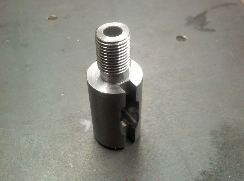 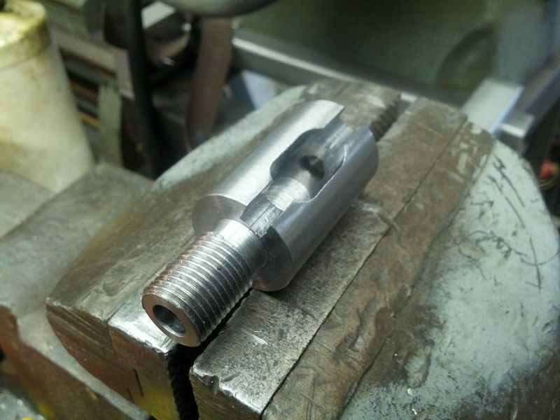 Like most bolt actions it screws into the body behind the cam. Honing the 1/4” hole: 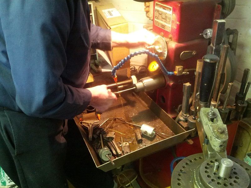 The cocking piece links the trigger mechanism to the firing assembly. This is a fundamental part of the action and is often neglected. Lug seating, bolt clearance, and lock time get most of the attention...but trust me, pin release is even more critical. We want consistent trigger engagement, a clean break, adequate support, and no drag. Lofty goals, but if firing pin actuation varies, precision will suffer. Dad’s blueprinting is pretty rough: 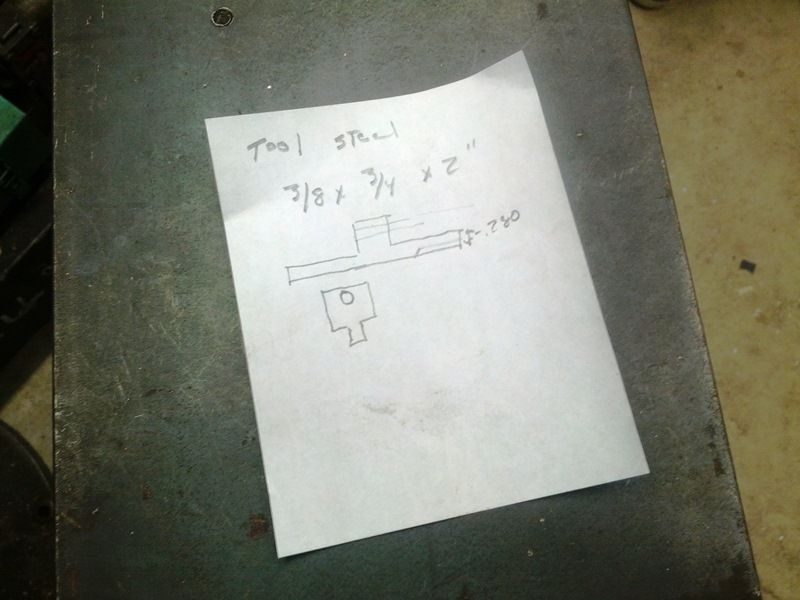 A more technical view of the cocking piece: 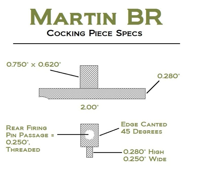 Starrett surface ground square stock is the basis for the insert: 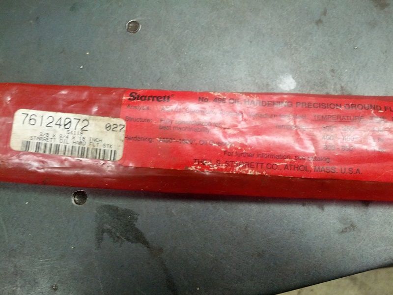 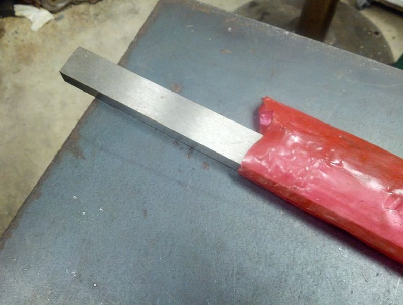 A 2.0” section was cut in a band-saw: 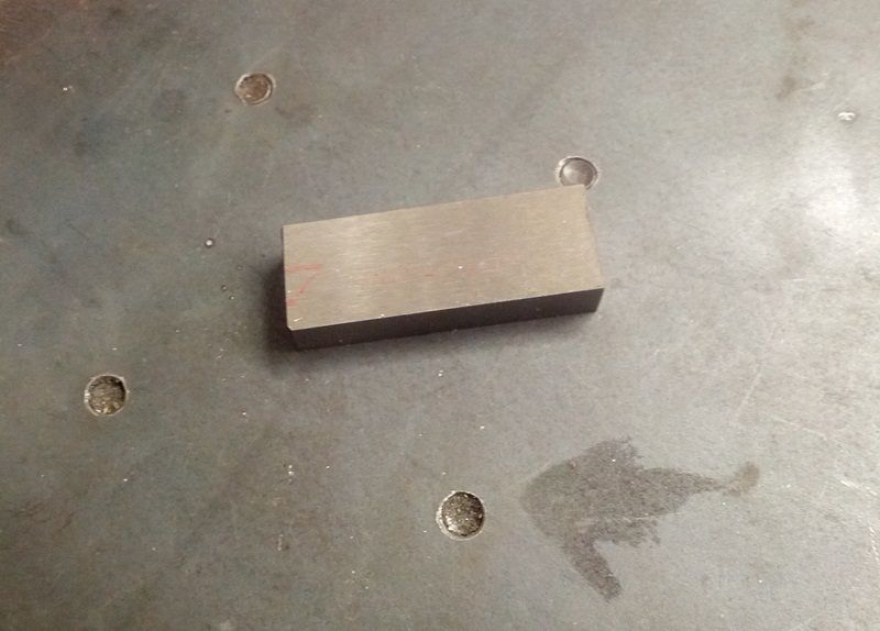 Milling the end flats: 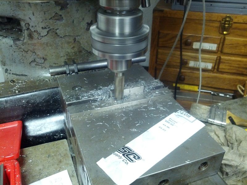 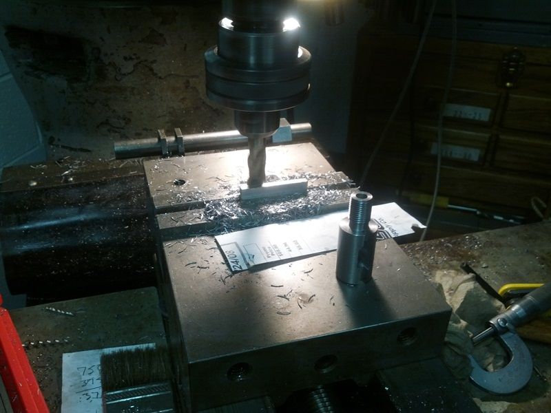 [ 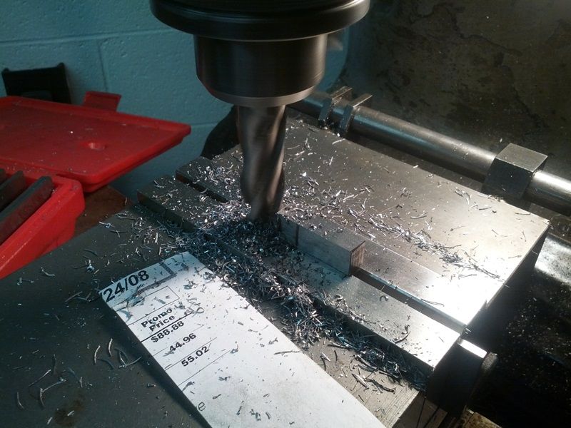 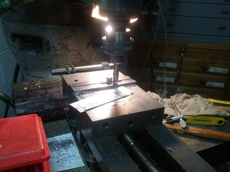 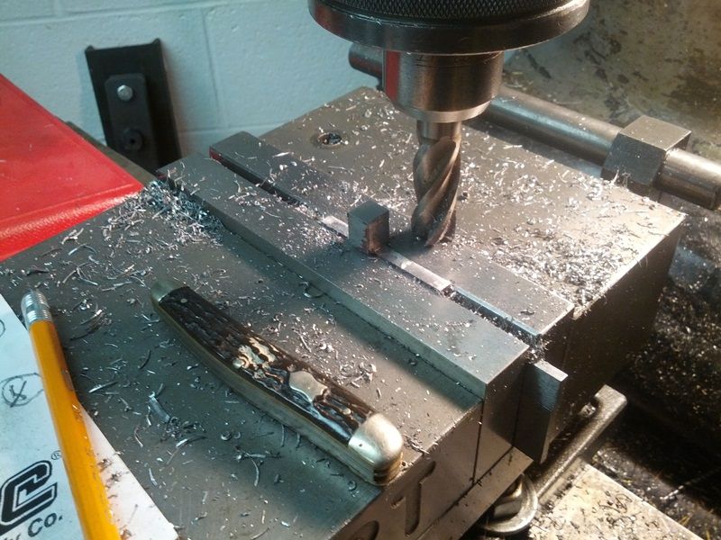 Testing the cocking piece in the shroud: 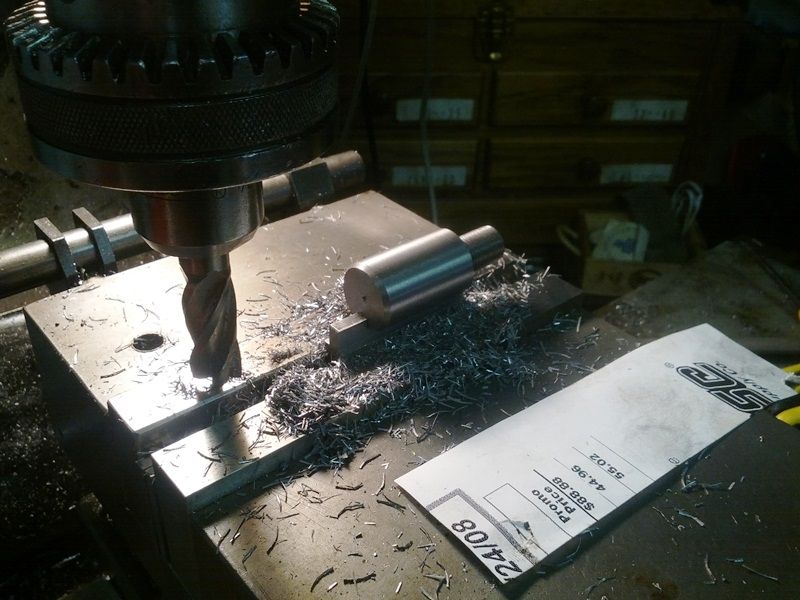 The insert next and the threaded body: 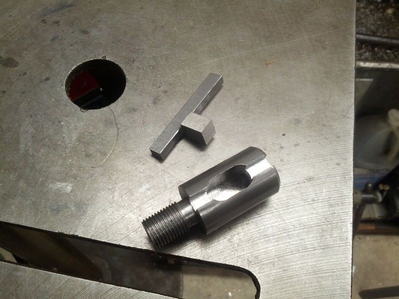 Square edges don’t mate well with radiused corners. Since the piece slides in the shroud, we’ll cant the sides by 45 degrees. An electronic angle sensor pinpoints the pitch: 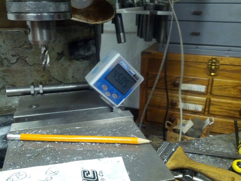 An end-mill is fed in 0.200”: 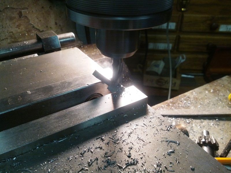 The yet to be polished and undrilled cocking piece: 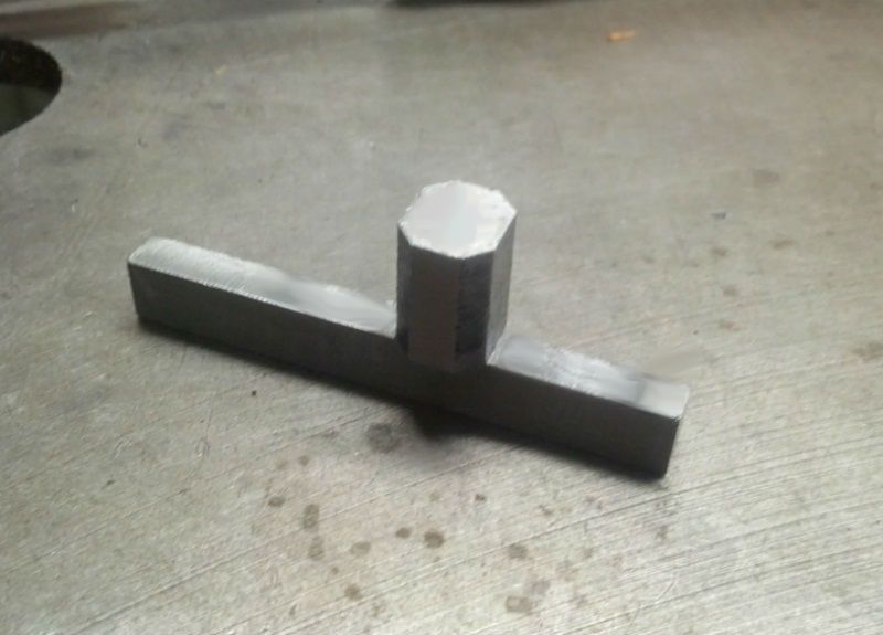 Fit to the shroud. Note we haven’t trimmed it to final length yet: 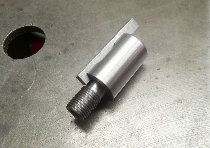 -Lee www.singleactions.com"Building carpal tunnel one round at a time" |
|
|
|
Post by curmudgeon on Feb 20, 2014 16:40:34 GMT -5
LEE, a little off subject and hope not too personal. Why an CE rather than a ME  |
|
|
|
Post by Lee Martin on Feb 20, 2014 16:47:21 GMT -5
Lee, are you referring to engineering degrees? If so, the answer is neither. My dad and I both have undergrads in chemistry. He practices medicine for a living, I practice finance. And with healthcare regulation going the way it is, he tells me everyday I made the better choice.... -Lee www.singleactions.com"Building carpal tunnel one round at a time" |
|
|
|
Post by curmudgeon on Feb 20, 2014 21:30:03 GMT -5
Yes I understood your undergrad was Chemistry just thought a CE. And knew your Dad was a MD. both ungergrads can go anyway I guess. My urologist undergrad was West Point, USMA Kent Lomont was a EE, but later got a Doctorate when the machine gun business slowed a couple years back. Interesting. Poor Kent left us a year ago last Jan, bone cancer. I asked him about recoil of some of his 200 plus ft. lb. recoil behemouths? He said NO his bull riding days during undergrad years at Notre Dame. Broke everybone in his body over time, some more than once. Never slowed him down tho till the very end.
|
|
|
|
Post by Lee Martin on Feb 26, 2014 14:38:23 GMT -5
Step 29 – Firing Pin Protrusion _________________________________________ The PPC craves high operating pressure, thresholds far above the SAAMI cap. Their rating only applied to the short-lived 6mm PPC USA by Sako and was ~58,000 PSI. Benchresters ignore that recommendation and load between 60,000 and 70,000 PSI. While high for commercial makes, 70,000 PSI is doable in these close tolerance race guns. Secondly BR primers, CCI BR-4’s and Federal 205M’s to be exact, safely contain these tunes with thicker cups (standard small rifle = 0.0020”, Fed 205M = 0.00225, CCI BR-4 = 0.0025”). Precision notwithstanding, primer strike becomes more acute at these levels. The firing pin tip must be rounded and the correct size. Flat, pointed, or sharply curved can get you into trouble as will diameters over 0.075”. Trust me, 65,000+ PSI and an abrupt profile will pierce these suckers. Excessive spring pressure also leads to blanking and for that reason I stay under 24 lbs. We’ll be fitting the main spring soon and I’ll share the calculation. That spring poundage further ties to the lock-time derivation. Pin protrusion is up next. Again, we use an adjustable collar that’s set to 0.055”. That means the tip extends fifty-five thousandths past the bolt face upon firing. But measuring it is tricky. Since the pin is countersunk within the bolt there’s no easy way to mic it. So dad built a small gauge to check protrusion and it works well: 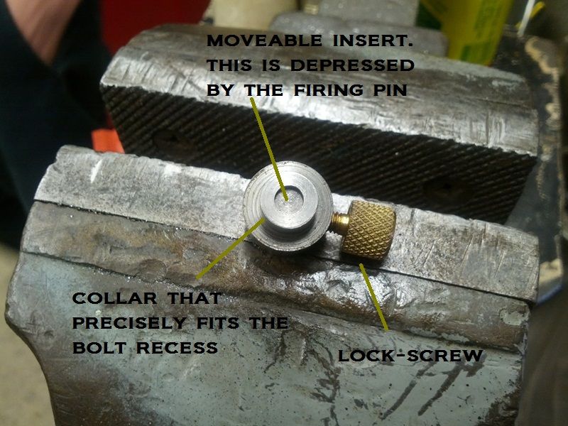 You start by loosening the set-screw and pushing the insert flat against the back edge. The collar is head specific and fits the bolt face when the assembly is fired. As the pin touches the insert it pushes it out by the protruded amount. You’ll notice this as it sticks past the rear. When flush the gauge is 0.700” in length, or your zero. The difference between that and the engaged insert gives the pin protrusion. 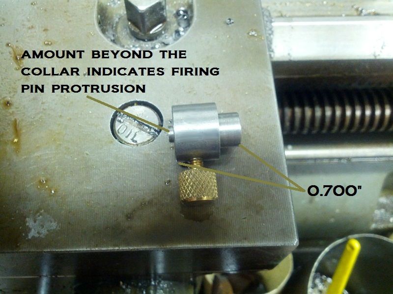 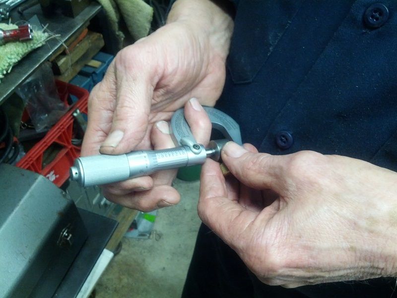 -Lee www.singleactions.com"Building carpal tunnel one round at a time" |
|
paulg
.375 Atomic
  
Posts: 2,420
|
Post by paulg on Feb 26, 2014 15:14:20 GMT -5
Yeah but can y'all make a whistle out of a piece of bamboo? Very impressive! Make 'em then shoot 'em! While y'all are making world class firearms I'm watching The Fox and the Hound with the grandson.  |
|
|
|
Post by bradshaw on Feb 26, 2014 15:55:59 GMT -5
Lee.... " excessive spring pressure also leads to blanking."
Wasn't aware of that. Very unlikely we'll ever encounter excess mainspring pressure in a revolver----it would be very difficult to cock and certain the peen the gun. We encountered PRIMER BLANKING with the standard Blackhawk mainspring in prototype .357 Maximums. Bill Ruger, Jr., was ready to make special springs, but decided to try the heavier Cap & Ball mainspring first. It worked.
The Blackhawk mainspring delivered an uneven indent to the stiff Remington Small Rifle Primer, so the heavier Old Army C&B mainspring was better for igniting the rifle primer, and for holding the primer cup against blanking.
David Bradshaw
|
|
|
|
Post by Lee Martin on Feb 26, 2014 16:44:59 GMT -5
" excessive spring pressure also leads to blanking." Kind of goes against conventional thinking, doesn't it? We all know too light a mainspring can cause rebound and piercing at high pressure. Oddly, in the early days of the PPC they ran real heavy bolt springs to reduce lock-time. At the upper-end of the pressure curve (ie, 70,000 PSI), the small rifle primers sometimes blanked. Many benchresters reported that when they dropped the poundage the problem went away. Nowadays most guys use springs between 18 and 28 pounds. -Lee www.singleactions.com"Building carpal tunnel one round at a time" |
|
|
|
Post by Lee Martin on Feb 27, 2014 16:12:50 GMT -5
Step 30 – Fitting the Cocking Piece ______________________________________ The cocking stub is drilled and tapped for the firing pin. This has to be done in perfect alignment with the shroud or it’ll pinch during travel. We put the cocking slide in the shroud and locked them in Bridgeport. Centering devices indicate the mid-point. 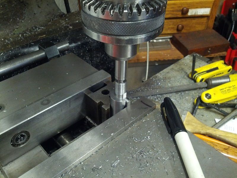 This was further validated with a test dowel. 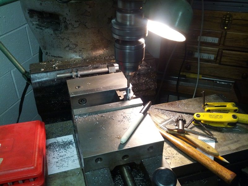 A number 3 (0.2130”) drill made the hole. As you’ll see, we line-bored it through the shroud: 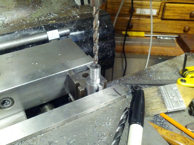 The cocking piece was tapped but only at the stub. Because the shroud is bored 0.250”, faint thread imprints unavoidably appear in the stem. We’ll remove them via honing at a later stage. 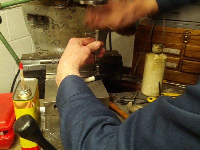 Cleaning-up the threads: 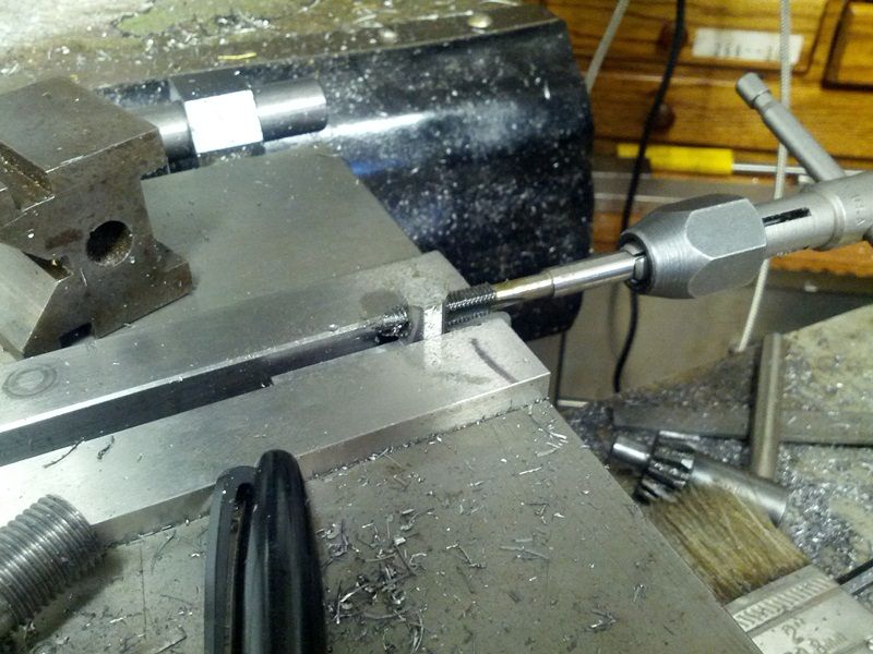 Our firing pin is then cut to length: 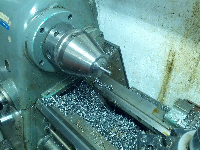 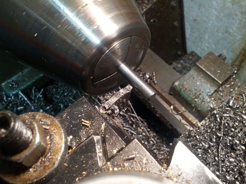 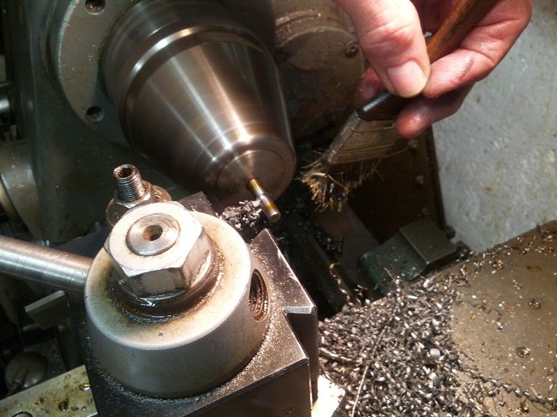 Here’s a shot of the bored and threaded cocking piece: 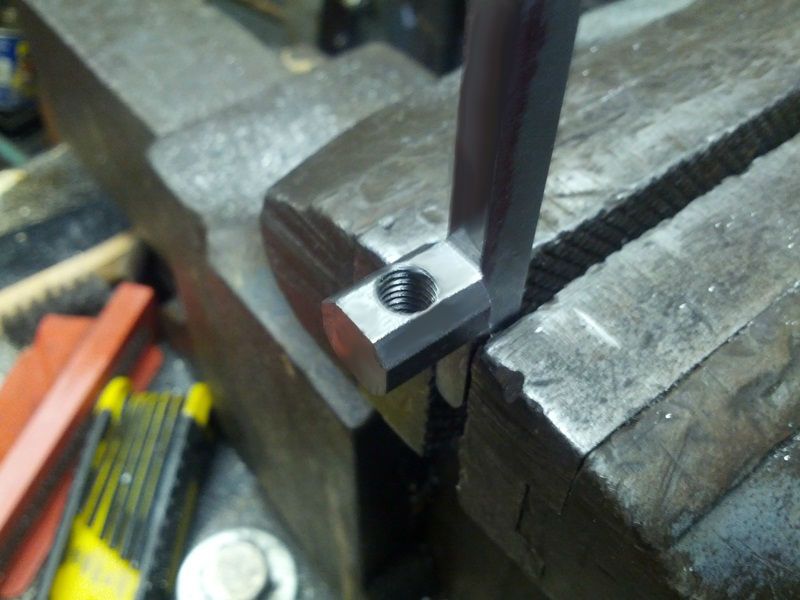 The underside also has to be drilled and tapped for a set-screw. Like so many steps in this project, that too is done in a vertical mill: 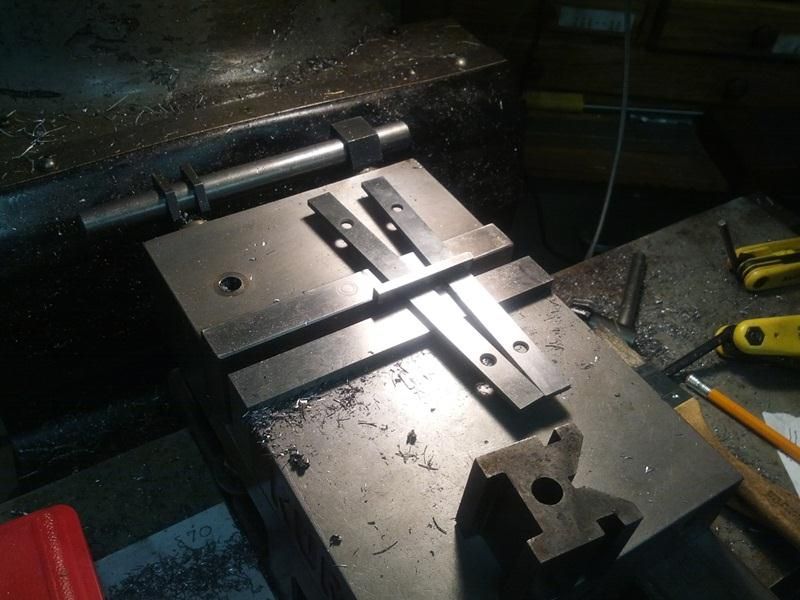 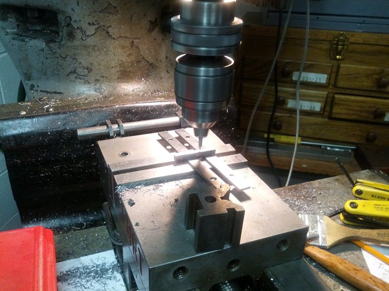 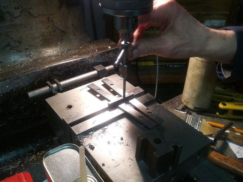 -Lee www.singleactions.com"Building carpal tunnel one round at a time" |
|
|
|
Post by tangocharlie on Feb 27, 2014 16:20:39 GMT -5
Lee;
To the mechanically challenged (me) this thread and the individual steps are nothing short of incredible. I know it is just another day in the shop to you, but to folks like me it is the opportunity to see inanimate metal actually take life. I thank you for sharing this. TC
|
|
|
|
Post by Lee Martin on Feb 27, 2014 16:25:02 GMT -5
Glad you like it. I know some of this documentation can be long and dry. It doesn't interest the masses. Even so, I'd like to get more threads around "why" and "how" on this forum. Many thanks for looking. -Lee www.singleactions.com"Building carpal tunnel one round at a time" |
|
paulg
.375 Atomic
  
Posts: 2,420
|
Post by paulg on Feb 27, 2014 16:47:26 GMT -5
Glad you like it. I know some of this documentation can be long and dry. It doesn't interest the masses. Even so, I'd like to get more threads around "why" and "how" on this forum. Many thanks for looking. -Lee www.singleactions.com"Building carpal tunnel one round at a time" To the contrary, for me anyway. I find it very fascinating! I appreciate the dedication y'all put into your projects. All the fellas that take the time to document their work here I very much enjoy. I would like to see Rob,Mike and Craig do something like this with one of their shucks. |
|
|
|
Post by Lee Martin on Mar 3, 2014 15:05:28 GMT -5
Step 31 – Installing the Firing Pin __________________________________________________ A geometric die head threads the end of the shaft. Video of it in action: The firing pin with the collar adjusted for 0.055” protrusion. 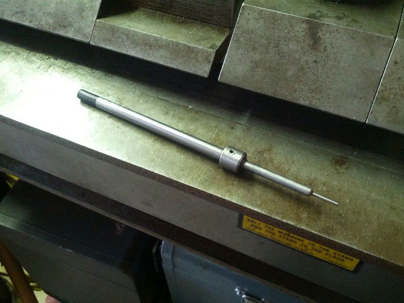 Before assembling the bolt we honed the shroud inlet a few thousandths over 0.250”. The cocking piece should support the pin but only act as a rough guide. Our goal is to have it travel straight through the hole without the threat of drag. The bolt insert with a very light test spring: 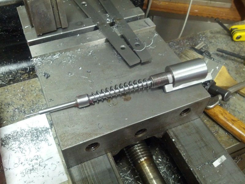 The cocking piece must move unimpeded, even slight resistance can hurt accuracy. And this is where hand fitting comes into play. Filing, stoning, polishing and testing is done repeatedly until perfect. You have to be very patient at this stage. Test fit: 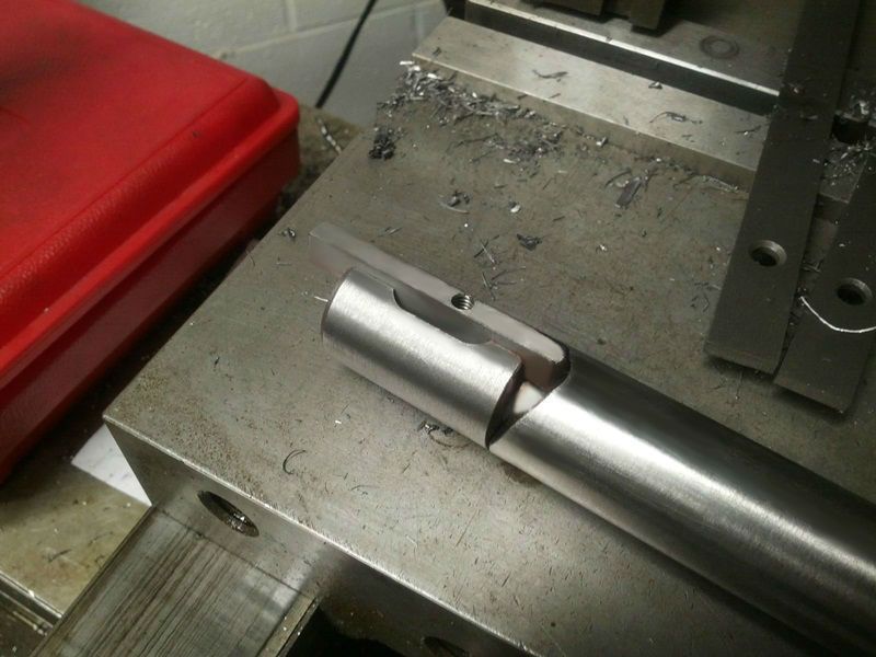 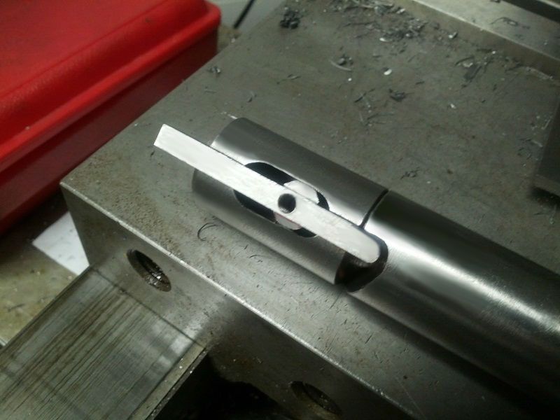 This shows the key bearing points: 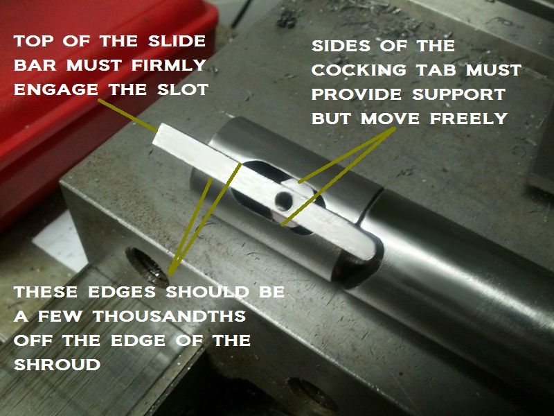 Notice how the cocking tab edges and the top of the slide do the guiding. -Lee www.singleactions.com"Building carpal tunnel one round at a time" |
|


